BAILII is celebrating 24 years of free online access to the law! Would you consider making a contribution?
No donation is too small. If every visitor before 31 December gives just Β£1, it will have a significant impact on BAILII's ability to continue providing free access to the law.
Thank you very much for your support!
[Home] [Databases] [World Law] [Multidatabase Search] [Help] [Feedback] | ||
England and Wales High Court (Patents Court) Decisions |
||
You are here: BAILII >> Databases >> England and Wales High Court (Patents Court) Decisions >> Evalve Inc & Ors Edwards Lifesciences Ltd [2020] EWHC 514 (Pat) (12 March 2020) URL: http://www.bailii.org/ew/cases/EWHC/Patents/2020/514.html Cite as: [2020] RPC 12, [2020] EWHC 514 (Pat) |
[New search] [Printable PDF version] [Help]
BUSINESS AND PROPERTY COURTS OF ENGLAND AND WALES
INTELLECTUAL PROPERTY LIST (ChD)
PATENTS COURT
The Rolls Building 7 Rolls Buildings Fetter Lane London EC4A 1NL |
||
B e f o r e :
____________________
(1) EVALVE INC. (2) ABBOTT CARDIOVASCULAR SYSTEMS INC. (3) ABBOTT MEDICAL U.K. LIMITED |
Claimants |
|
- and - |
||
EDWARDS LIFESCIENCES LIMITED |
Defendant |
____________________
Iain Purvis QC, Piers Acland QC, and Kathryn Pickard (instructed by Powell Gilbert) for the Defendant
Hearing dates: 9th - 13th, 17th and 18th December 2019
____________________
Crown Copyright ©
Mr Justice Birss :
The witnesses
The person skilled in the art
The common general knowledge
Long felt want, commercial success and statements of case
"I have not taken into account the unpleaded commercial success argument advanced by Olaplex, including the cross- examination materials referring to the Holy Grail and some parts of Mr Christal's testimony. The evidence does suggest that maleic acid or derivatives of it do have some genuine effect to reduce hair damage cause by oxidation, but that just goes to show that the invention works and so there is no insufficiency. Whether it is all worth the social media hype is quite another matter and so too is whether any of that properly establishes a long felt want. This was another transparent attempt to avoid the clear provisions in the rules "
"what is the defect [in the prior art], if there be one, how it was overcome and whether long-felt want is being sought to be established and, if so, how the plaintiffs are going to say they are going to establish it"
The 850 patent
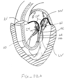
"The most common treatments for mitral valve regurgitation rely on valve replacement or strengthening of the valve annulus by implanting a mechanical support ring or other structure. The latter is generally referred to as valve annuloplasty. A recent technique for mitral valve repair which relies on suturing adjacent segments of the opposed valve leaflets together is referred to as the "bow-tie" or "edge-to-edge" technique. While all these techniques can be very effective, they usually rely on open heart surgery where the patient's chest is opened, typically via a sternotomy, and the patient placed on cardiopulmonary bypass. The need to both open the chest and place the patient on bypass is traumatic and has associated morbidity."
Claim construction the 850 patent
"[0052] In many embodiments, the distal elements are individually extendable, retractable and repositionable. Fig. 13 illustrates the extension of a first element 230 independently of the second element 232. Such elements 230, 232 may be utilized in this arrangement or the second element 232 may be extended at any point during the procedure."
"4. A device according to claim 1, wherein each of the distal elements and each of the proximal elements is independently extendable, retractable and repositionable."
Inventive step over Deem
What works and what doesn't
The obviousness case
i) The distal end of the ribbon is mounted to the innermost shaft (725) at the end at point 730.
ii) The midpoints of the ribbon on either side are mounted on the end 731 of the central shaft (726).
iii) The proximal ends of the ribbon on either side are attached to end 732 of the outermost shaft (727).
Added matter
i) a capture device detachably connected to an interventional catheter in which both the proximal and distal elements are movable between a retracted position adjacent the shaft of the catheter and an extended position extending away from the said shaft (in effect feature F of claim 1);
ii) a capture device in which the proximal and distal elements are movable between a retracted position adjacent the shaft of the capture device and an extended position extending away from the said shaft (in effect feature F of claim 11);
iii) a capture device comprising a shaft having a proximal end and a distal end with proximal and distal elements disposed near the distal portion of the said shaft (in effect feature E of claim 11).
"In a number of embodiments, an example of which is shown in Figs. 17A-17D, the interventional tool 204 also comprises proximal elements 240, 242 which are capable of protruding radially outward from the shaft at a location which is proximal to the elements 230, 232 previously described. The proximal elements 240, 242 may have any of the forms, shapes, material compositions, features, or capabilities described in relation to the distal elements 230, 232."
Infringement
closed elongated
The 810 patent
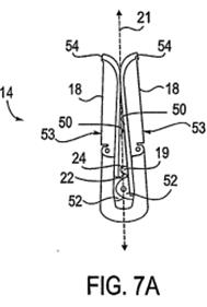
Fig 7A - Closed / Delivery position Fig 7B Open position
Fig 7D Inverted position
"[0062] Under some circumstances, it may be further desirable to withdraw the fixation device 14 back through the valve or completely from the patient following initial insertion through the valve. Should this be attempted with the clip in the closed or open positions illustrated in Figs. 7A-7C, there may be a risk that arms 53 could interfere or become entangled with the chordae, leaflets or other tissues. To avoid this, the fixation element 14 is preferably adapted for inversion of arms 53 so that free ends 54 point in a second direction, opposite to the first direction in which the free ends 54 pointed in the closed position, each arm 53 forming an obtuse angle relative to axis 21 as illustrated in Fig. 7D. The arms 53 may be rotated so that the engagement surfaces 50 are disposed at a separation angle 56 of up to 360 degrees, and preferably at least up to 270 degrees."
Figure 9 Figure 11B
Claim construction the 810 patent
Infringement
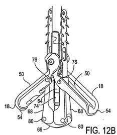
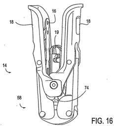
The way the PASCAL device works
closed position capture ready position
captured position elongated or reposition position
The easy subsidiary claims and Modified Conditional Amendment F
Claim 1 - Abbott's primary case
"The devices [the patent and PASCAL] provide a different solution to the same problem. The fixation elements do not invert around a hinge point at the shaft. They bend in the middle. So rather than invert into a position for withdrawal, they flatten and extend into a position for withdrawal, just as with the Goldfarb Fig 18 embodiment. This is not the invention claimed. It does something different (elongate rather than invert) in a different way (by pulling the two axially fixed ends apart). It is not surprising that it cannot be fitted into the claim. The equivalence case comes down to a general assertion that the device achieves something similar to the 810 Patent in that PASCAL can also be put into a position where it is suitable for removal. That is plainly not good enough."
[closing paragraph 50]
Claim 1 -Abbott's secondary case (and whether it is open)
Claims 18 and 19
Validity
Novelty - Goldfarb
Inventive step
The law embodiments as starting points
"182. The defendants also relied on Brugger v Medicaid for the proposition that "the mere existence of alternatives is not in itself an argument against obviousness". I agree that the mere existence of obvious alternatives is not in itself an argument against obviousness. Before Brugger was decided there was sometimes a tendency to place too much emphasis in argument about alternatives as if they always established inventiveness, on the other hand undue focus on Brugger itself can mislead too, discounting alternatives altogether. The correct proposition about alternatives is the statement of Kitchin J in Lundbeck [2007] RPC 32 approved in Conor [2008] UKHL 49 which I have cited above. It is an important statement because it is a balanced one. "
"The question of obviousness must be considered on the facts of each case. The court must consider the weight to be attached to any particular factor in the light of all the relevant circumstances. These may include such matters as the motive to find a solution to the problem the patent addresses, the number and extent of the possible avenues of research, the effort involved in pursuing them and the expectation of success."
The facts
(1) The implant must be detachable i.e. capable of being detached from its delivery device and left in situ.
(2) The device must be able to capture and hold the valve leaflets securely and permanently without causing significant trauma or damage to the valve leaflets.
(3) The implanted device must not embolize i.e. become detached, causing an arterial blockage.
(4) The device must be redeployable, that is to say the operator must be able to reposition the device so to achieve optimal valvular function before it is finally implanted. In other words a 'one-shot' design would be unsuitable.
(5) Chordal entanglement/entrapment or damage to other tissue or leaflets should be avoided.
(6) The valve leaflets should be held together in a manner that resembles normal coaptation, in other words there should be anatomically accurate repair.
(7) The delivery profile must be sufficiently small to enable the device to pass through the vasculature of the patient and the general rule is 'smaller is better'.
(8) Avoiding interference with the chordae. If implanting via the antegrade approach, it would be desirable to be able to withdraw the device back into the atrium before attempting another leaflet capture in order to avoid interference with the chordae.
(9) Removability. If cardiac function cannot be improved, it would be desirable to have the option of removing the device entirely from the patient without causing significant damage to the heart itself.
(10) It would be highly desirable to cover the device with a material that allows endothelial growth into the fabric, thereby helping to anchor the device in place and reducing thrombogenicity.
What would the skilled team make of Goldfarb
Device geometry
Nitinol issues
Making figure 18 detachable
Figure 5 Figure 6
Detachability and enabling disclosure
Other features
Obviousness conclusions
Claim 1 - equivalents
Question 1: does the variant achieve substantially the same result in substantially the same way as the invention?
Question 2: Would it be obvious to the person skilled in the art, reading the patent at the priority date, but knowing that the variant achieves substantially the same result as the invention, that it does so in substantially the same way as the invention?
Question 3: Would such a reader of the patent have concluded that the patentee nonetheless intended that strict compliance with the literal meaning of the relevant claim(s) of the patent was an essential requirement of the invention?
Actavis question 1
"The first Improver question, whether the variant has a material effect on the way the invention works, was addressed by Lord Neuberger at [60]. He thought this was generally satisfactory but the court must focus on "the problem underlying the invention", "the inventive core", or the "inventive concept". In effect the question is whether the variant achieves the same result in substantially the same way as the invention".
Actavis question 2
Actavis question 3
Equivalents - conclusion
Amendment
Conclusion
Annex 1: The claims of the 850 patent
A A device adapted for repairing a cardiac valve in a patient, the cardiac valve having leaflets,
said device comprising:
B an interventional catheter comprising a shaft having a proximal end, a distal end and a longitudinal axis therebetween, configured to pass to a position within the heart adjacent to the cardiac valve;
and
C a capture device detachably connected to the catheter
comprising
D at least two extendable distal elements and at least two extendable proximal elements,
E each of the proximal and distal elements being disposed near the distal portion of the shaft
and
F being moveable between a retracted position adjacent the shaft and an extended position extending away from the shaft for capturing the valve leaflets;
characterized in that
G the at least two distal elements and the at least two proximal elements are independently extendable, retractable and repositionable
H so that they are adapted to be extended or retracted by various amounts for protrusion of various distances from the shaft.
A device as in claim 1, wherein the at least two proximal elements are interlockable with the at least two distal elements.
A A capture device for repairing a cardiac valve having valve leaflets,
the capture device comprising
B a shaft having a proximal end and a distal end;
C a coupling mechanism disposed near the proximal end of the shaft for coupling with an interventional catheter;
and
D at least two extendable distal elements and at least two extendable proximal elements,
E the proximal and distal elements being disposed near the distal portion of the shaft
F and being moveable between a retracted position adjacent the shaft and an extended position extending away from the shaft for capturing the valve leaflets;
characterized in that
G the at least two distal elements and the at least two proximal elements are independently extendable, retractable and repositionable
H so that they are adapted to be extended or retracted by various amounts for protrusion of various distances from the shaft.
A capture device as in claim 11, wherein the at least two proximal elements are interlockable with the at least two distal elements.
Annex 2: The claims of the 810 patent
A A fixation device for engaging tissue
comprising
B a pair of fixation elements each having a first end, a free end opposite the first end, and an engagement surface therebetween for engaging the tissue,
C the first ends being movably coupled together such that the fixation elements are moveable between 1) a closed position wherein the engagement surfaces face each other, and 2) an inverted position where the engagement surfaces face away from each other;
and
D an actuation mechanism coupled to the fixation elements adapted to move the fixation elements between the closed position and the inverted position,
E further comprising a pair of gripping elements, each gripping element moveable with respect to one of the fixation elements and being disposed in opposition to one of the engagement surfaces so as to capture tissue therebetween,
wherein
F the gripping elements are moveable from an undeployed configuration in which each gripping element is separated from an opposing engagement surface, to a deployed configuration in which the gripping element is adjacent to the opposing engagement surface
and wherein
G each fixation element is at least partially concave and each gripping element is at least partially recessed within the fixation element in the deployed configuration
or wherein
H the gripping elements are approximately parallel to each other in the undeployed configuration.
A fixation device as in claim 1, wherein the fixation elements are further moveable to an open position between the closed position and the inverted position.
A fixation device as in claim 1, wherein the gripping elements have frictional features configured to enhance grip on tissue engaged thereby.
The fixation device of any one of the preceding claims, further comprising a coupling member for detachably coupling the fixation device to a delivery device.
The fixation device of any one of the preceding claims, further comprising a covering on the fixation elements adapted for promoting tissue growth.
A fixation device as in any one of the preceding claims, wherein the fixation elements have longitudinal edges between the first end and the free end, the longitudinal edges being curved about a longitudinal axis away from the engagement surfaces.
A fixation device as in any one of the preceding claims, wherein the free ends of the fixation elements curve away from the engagement surfaces about a transverse axis generally parallel to the engagement surface, wherein the free ends of the fixation elements are curved about a second axis not parallel to the transverse axis.
A A fixation device for engaging heart valve tissue for the repair of a valve of the heart
the fixation device comprising
B a pair of fixation elements each having a first end, a free end opposite the first end, and an engagement surface therebetween for engaging the tissue,
C the first ends being movably coupled together such that the fixation elements are moveable between 1) a closed position wherein the engagement surfaces face each other, and 2) an inverted position where the engagement surfaces face away from each other, wherein in the inverted position the engagement surfaces provide an atraumatic surface to deflect tissue
and
D an actuation mechanism coupled to the fixation elements adapted to move the fixation elements between the closed position and the inverted position,
E further comprising a pair of gripping elements, each gripping element moveable with respect to one of the fixation elements and being disposed in opposition to one of the engagement surfaces so as to capture tissue therebetween,
wherein
F the gripping elements are moveable from an undeployed configuration in which each gripping element is separated from an opposing engagement surface, to a deployed configuration in which the gripping element is adjacent to the opposing engagement surface
and wherein
G each fixation element is at least partially concave and each gripping element is at least partially recessed within the fixation element in the deployed configuration
or wherein
H the gripping elements are approximately parallel to each other in the undeployed configuration.